At an asphalt mixing plant the aggregate material is stockpiled according to grain size and type. This material is usually loaded into the individual hoppers by a wheel loader. The minerals are dispensed via dosing belts (normally frequency-controlled) onto the collecting belt below, specific to the recipe. In this way, a corresponding cold feed recipe is generated on the collecting belt. The material is then transported to the dryer drum via this collecting belt
DRYER DRUM
The dryer drum is known as a rotary dryer. Here, the material is dried and heated for further processing. For the manufacture of asphalt, it is essential to remove the moisture from the base material to ensure bonding with the bitumen. Designed at an appropriate inclination, it transports the material through the entire drum via rotary movements. Lifter plates in the drum provide a thick material curtain in the drum, enabling efficient heat exchange. In addition to the dusts produced, water vapour is also generated during this drying or heating of the aggregate. In order to keep heat losses to a minimum during the drying process, the drum tube is insulated against heat radiation.
BURNER
The burner used for drying and heating can be operated with Diesel / LDO (Light Diesel Oil/F0 (Furnace Oil). During operation, the operator can change the combustible with the help of his controls.
DUST COLLECTION SYSTEM
The flue gas produced in the dryer drum and other exhaust air from the production process are extracted under vacuum and cleaned in the fabric filter. The flue gas is fed to the pre-separator of the filter together with the water vapour. The coarse particles of exhaust gas are separated in this pre-separator we deflection and by slowing down the flow speed. This coarse filler is fed directly back into the mixing process via screw conveyor. The fine fraction of exhaust gas, known as fine filler, is cleaned in the actual filter housing. The filter cloth gradually becomes dogged with dust particles, so it is periodically deducted by a scavenging air fan. The fine filler generated is collected In the dust collecting trough beneath the finer housing and forwarded via a screw conveyor installed in the trough and subsequently deposited in the reclaimed filler silo.
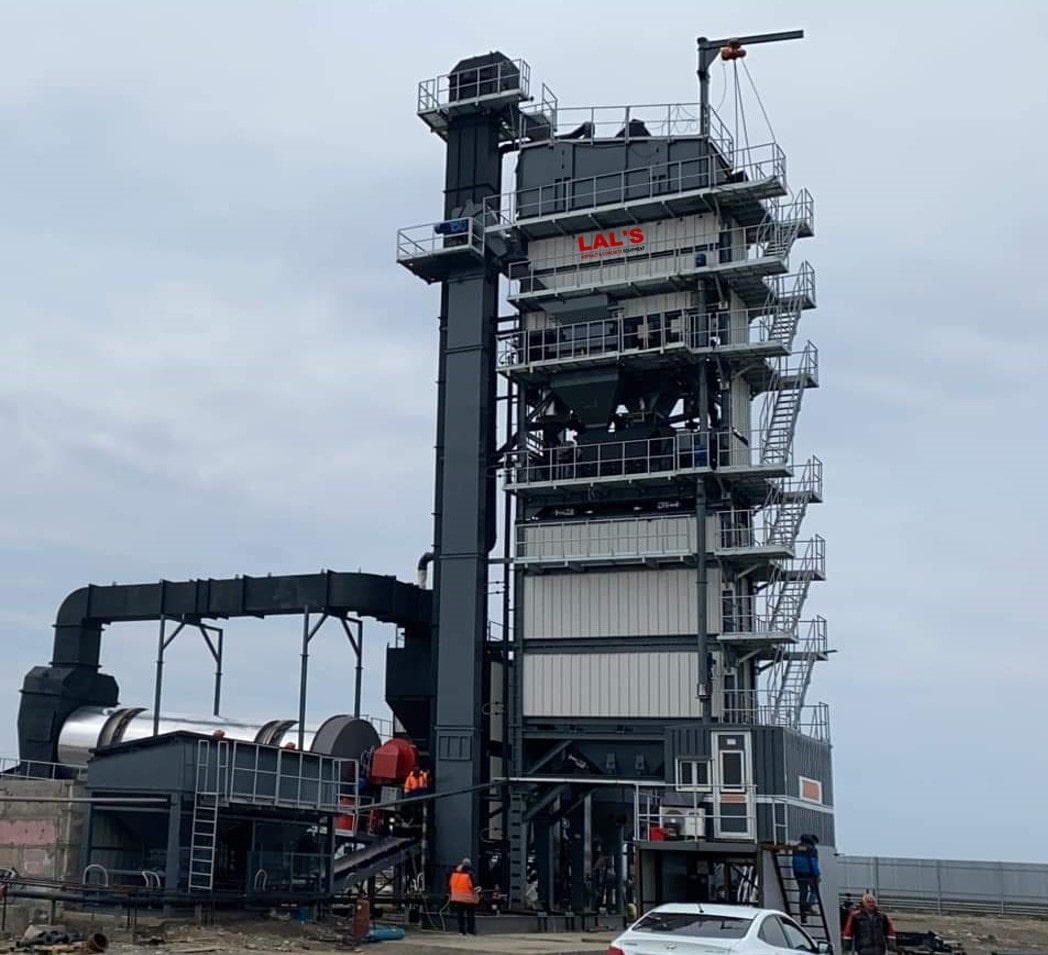
SCREENING AND MIXING TOWER
The actual mixing process takes place In the scrolling and remixing tower. The materials described in the upstream process arrive at the mixing tower screen via a hot stone elevator. The hot aggregate material is uniformly supplied to the screens screening decks. The screen is activated via two unbalance motors, stimulating the screen unit, and thus the screens, Co vibrate vertically. The input material is thus divided into the individual fractions and separated according to grain sire, stocked in the respective compartments of the hot bin section below.
MIXING AND WEIGHING SECTION
The mixing and weighing section is one of the core elements of an asphalt mixing plant. This is where the actual mixing process takes place. From the for bin section the hot material, stocked according to grain slze, is dispensed Into the aggregate weigh hopper below corresponding to the mixing recipe. The aggregate weigh hopper is mounted on load cells to facilitate the weighing. The individual fractions are weighed sequentially, i.e. the discharge doors open consecutively and dispense the present quantity of the respective grain into the aggregate weigh hopper. The weighing of the bitumen and the filler is carried out in parallel to the weighing of the aggregate material in the aggregate weigh hopper. The bitumen is weighed in the bitumen weigh hopper and dispensed into the mixer. The required filler is weighed in the filler weigh hopper, which is mounted on load cells, and delivered into the mixer via an inlet screw conveyor.
FILLER SILO
Both the filler reclaimed from the plant and the imported filler are stored in filler silo. Only the reclaimed filler is necessary for the basic function of an asphalt mixing plant. There is also the option of storing and using imported filler (foreign filler). The filler then arrives at the mixing tower for further processing via a filler elevator and a Screw conveyor.
BITUMEN SYSTEM
The bitumen binder is a core component of the asphalt. The different types of bitumen, tailored to its relevant intended use, are stared separately in appropriate thermally-insulated bitumen tanks. These are heated in order to maintain the required temperature of the bitumen, approx. 160 - 180 °C. These days bitumen tanks are heated almost exclusively via electricity, with a feasible alternative being tanks also heated by thermal oil. This means that the energy from the hot thermal oil is transferred to the bitumen via heat exchangers. The hat bitumen is removed from the tanks via a pump and conducted to the bitumen weigh hopper via heated and insulated pipelines. The tanks are filled by tanker lorry via a fill pump, through pipelines into the respective tank.
COMMAND CABIN
A command cabin for operating personnel is available to control the processes of an asphalt mixing plant. The operating menu for the entire mixing plant is installed in this cabin. From here, all drives can be started in manual mode. Here, all data required for the mixing process is collated and displayed. As well as managing the required recipes and monitoring or implementing the mixing process, operating personnel can also control.
FOUR BEEN FEEDER
At an asphalt mixing plant the aggregate material is stockpiled according to grain size and type. This material is usually loaded into the individual hoppers by a wheel loader. The minerals are dispensed via dosing belts (normally frequency-controlled) onto the collecting belt below, specific to the recipe. In this way, a corresponding cold feed recipe is generated on the collecting belt. The material is then transported to the dryer drum via this collecting belt