ASPHALT DRUM MIX PLANT
An asphalt drum mixing plant is a parallel flow continuous plant used for the manufacture of asphalt, macadam and other forms of coated road stone, sometimes collectively known as blacktop, hot mix or asphalt concrete.
The manufacture of hot mix demands the combination of a
number of aggregates, sand and a filler (such as stone
dust), in the correct proportions, heated, and finally
coated with a binder, usually bitumen based or, in some
cases tar. The temperature of the finished product must
be sufficient to be workable after transport to the
final destination. A temperature in the range of 100 to
200 degrees Celsius is normal.
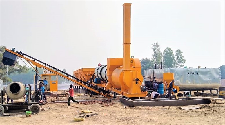
The asphalt drum mixing plant offered having designed roots from BARBER GREENE COMPANY in U.S.A.; generally conforming to Drum Mix series. It is modern having all essential features of a latest generation Hot Mix Plant for obtaining Hot Mix of designed quality for Road Construction works as well as in road repair and maintenance works undertaken for improving road surfaces. The plant offered is simple for erection, operation and maintenance with complete indigenous sophisticated and effective controls for efficient process control. The plant offered will meet all engineering specifications in construction and factor of safety provided as per norms.
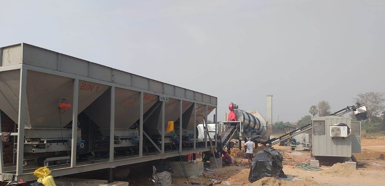
COLD AGGREGATE FEEDERThe cold aggregate feeder will have four independent bins or compartments of approximately 60 tons total capacity supported on a rigid steel frame. The feeder bins will be constructed of 5 mm thick steel plates. Each bin will be provided with a belt feeder under the bin driven by an independent and mutually synchronized 2 H.P. variable speed motor for feeding the aggregate at a uniform and predetermined rate through a precision adjustable bin quadrant gate. Each bin will deposit its aggregate on a gathering conveyor of 600 mm wide belt driven by 5 HP electric motor
SINGLE DECK VIBRATORY SCREENSingle deck vibratory screen is provided at the discharge end of the gathering conveyor to enable rejection of any oversize material above the permissible limit before loaded on the slinger conveyor and to the drier.
SLINGER CONVEYOR (FEED CONVEYOR)A slinger conveyor with 500 mm wide belt will be provided for transferring the aggregate received from the gathering conveyor and discharging it into dryer under combustion zone. The slinger conveyor will be driven by a 5 H.P. electric motor. A continuous electronic weigh-bridge with load cells will be mounting on the slinger conveyor for weighing accurately the aggregate. The equipment will monitor the weight of aggregate fed in the drum and indicate the same in tons per hour along with a cumulative read out and a totaliser.
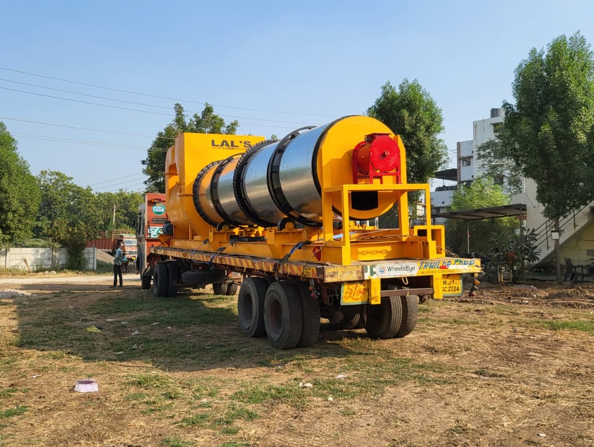
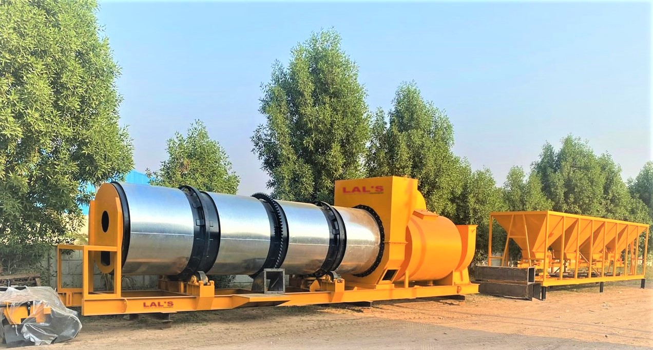
DRYER AND MIXING UNITThe dryer and mixing unit will be of a dual zone THERMO DRUM design, cylindrical drum mounted on a sturdy and robust steel structure. Fabricated from boiler quality plates of 10 / 12 mm thick, the THERMO DRUM will be divided into two energy zones; a Radiation Zone and a Convection/Coating Zone by a radiation shield. The greatest concentration of heating energy will be in the Radiation Zone where it will be applied to the cold, wet aggregate and most of the heating and drying will take place therein. Bitumen will be injected in the Convection/Coating Zone, which is protected from the direct flame of the burner by the radiate heat shield, and mixing; heating and drying will be completed. The dryer will be designed for maximum fuel efficiency and heat transfer while preventing blue smoke emission problems. It will produce a superior quality hot mix. The flights in the different zones will be designed exclusive and uniquely to work together to assure that a properly controlled veil of aggregate is maintained during operation. “The exterior of the THERMO DRUM shall be insulated with ceramic wool and cladding is done with stainless steel”. At the burner end, where super heating and drying takes place, special W shaped flights will be provided to create a veil of material surrounding the burner flame. This will help retain flame heat within the drum, provide more uniform drying, reduce drum shell temperatures and contribute to fuel efficiency. All drum flights will be designed to mix and move material through the drum at optimum rates and make a quality product with no sacrifice in production output. The dryer drum will be rotated by a cradle type chain drive, which is powered by an electric motor coupled to a fully enclosed precision gearbox. The drum will be supported on four-machine trunnion equipped with heavy-duty roller bearings. The trunnion will be adjustable for skew to keep the drum at correct operating position. Heavy-duty gearbox will be provided to control the rotational speed of the dryer drum. The dryer drum will be equipped with burner packages which include fully automatic high-pressure jet burner with auto on/off control. The burner will be capable of heating the aggregate to a temperature not less than 160oC without any un- burnt fuel or carbon residue on the aggregate and reducing the moisture contents to 0.5% by weight The drive to the dryer drum, and burner pump and blower will be interlocked, so that the burner can be lit only when dryer drum is rotating. The dryer and mixing drum will have a sweep discharge chute for giving an even and positive discharge from the side of the mixer. The dryer discharge chute will be so designed that it will discharge the material directly on the load out conveyor.
BITUMEN METERING SYSTEMThe bitumen metering system will include a skid mounted positive displacement bitumen jacketed pump with a variable speed A.C. motor drive. The motor drive will be synchronised with the aggregate feed to automatically achieve a specific rpm of the motor for a desired percentage of bitumen in the final mix. A scanner is provided in the control cabin to indicate the bitumen flow rate in litres per min.
MIX LOAD OUT CONVEYORTruck loading will be by an inclined load out conveyor with heat resistant belting, equipped with a surge hopper with hydraulically operated clamshell gate, to provide surge capacity when changing trucks and control segregation in the mix. The discharges height of the mix will not be less than 2 Mtrs. above ground level.
MINERAL FILLER SYSTEMMineral filler system will be provided to add the mineral filler from a hopper. A 1.5 /2 Ton capacity hopper will be fabricated of steel plates with loading doors. A pneumatic dust and filler conveying system will include a rotary valve with AC motor, adapter chute and with fines piping back to drum mixer and blower skid with compressor electric motor.
BITUMEN STORAGE TANKBitumen tank of 15 MT /20 MT /25 MT litres capacity will be provided. The tanks will be constructed of 5 mm thick steel plates and will be supported on rigid steel frames. The tanks will be equipped with separate burner for heating the bitumen, under effective and positive control at all the times, to the temperature requirements set forth in the specifications for the paving mixture. Heating will be accomplished by high-pressure burner suitable for operations on the light oil and single face power supply. The bitumen transfer pump shall be positive action gear type of adequate capacity to pump the hot bitumen. The pumps will be hot oil jacketed to keep the pumps hot and to avoid jamming due to drop in temperature. The pipelines carrying the hot bitumen will be suitably designed and provided with necessary heating arrangement and insulation. A hot oil circulating system for the bitumen will be provided off adequate capacity to provide for proper and continuous circulation between storage tanks, and mixer during the entire operating period. All the bitumen pipelines to and from the bitumen tanks, bitumen transfer and fittings will be hot oil jacketed and properly insulated to prevent loss of heat and clogging. The bitumen tanks will be fitted with a temperature indicator accurate to within +/- 3 degree Cel. to indicate the temperature of the bitumen. To prevent the heat losses due to radiation, the bitumen tanks will be effectively lagged with 50 mm thick, fibre glass wool (Crown 150) or equivalent, the lagging being protected and kept in position by suitable lagging plates or an equivalent to ensure that it does not deteriorate in use or becomes impregnated with the bitumen. The chimney for the bitumen tank will be off such a size that it will meet the statutory height regulations. The chimney will be fitted with a damper and a cowl to prevent entry of rainwater.
CONTROL CABIN AND OPERATING CONTROLSThe entire working of the plant will be fully automatic with provision for manual operation. A fully automatic centralised control panel with off/on push buttons, indication lights/gauges will be provided inside a cabin for switching on and off any of the drive motors of the plant independently and with interlocking relays. The metal fabricated cabin will be weather protected and dust proof with an automatically closing door and a one-piece window. All sides of the cabin will be provided with glass panels for all round vision; however, lower 3 feet portion will be lined with industrial decorative laminate. The cabin will have fully prewired interior lighting and fitted with an air conditioner. The floor will be laid with wooden planks and a suitable rubber mat will be provided for protection from electric shocks.
FINISHING AND PROTECTIONAll exposed parts of the plant will be cleaned, treated and painted with suitable anti corrosive protective paint conforming to the relevant Indian Standards (or equivalent). Electrical equipment, power units and parts subjected to high temperature will be painted with special paints suited for the purpose. The shades of approved colour code will be used to differentiate units of the plant and the pipelines. Electrical connections including terminal and circuit connections, components and circuit elements will be suitably treated to resist the growth to fungi.
MAINTENANCE TOOLS AND ACCESSORIESA strong toolbox with lock and key and containing necessary tools and accessories for normal maintenance adjustment and lubrication of the plant together with instructions and inventory of tools and necessaries will be provided. Provisions will be made for suitably affixing the toolbox on the machine. If the bidders recommended certain special tools, then, only the particulars would be filled in schedule of tools.
WET DUST COLLECTOR (WET TYPE POLLUTION CONTROL SYSTEM)A Venturi type-high efficiency wet dust collector will be provided. The wet dust collector will be designed to achieve a most efficient control for air pollution due to emission from exhaust chimney. An exhaust fan having sufficient capacity to ensure an effective airflow through the dryer and through the dust collecting system will be provided. The wet collector will be working on the principle of wetting the dust particles entered in the exhaust gases and trapping them in water droplets, which are drained from the system in the form of water sludge. The dust laden exhaust gas will be drawn from the drum mixer and into the venturi by the exhaust fan. At the venturi throat, the exhaust gas will pass through a water spray introduced by multiple nozzles. Dust particles in the exhaust stream will be "surrounded" by the water and wetted. The extreme turbulence in the venturi will promote very intimate contact of water and dust particles to assure thorough mixing. As the exhaust gas enters the separator, the dust-laden water will be removed by centrifugal action and skimmer blade. The dust-laden water will be drained out of the separator into a setting pond. Large spray nozzles will be provided clog free operation and assure minimum water make up requirements for venturi type collectors. Wide opening nozzle will easily allow dirty water to be recirculating without a lengthy clarification period. Deflector in nozzle will direct water stream into a full cone spray pattern for maximum wetting of dust particles. High pressure in the air stream will assure more efficient operation of venturi type collectors with less maintenance. Air stream will move more than double its rate of speed as it is forced through the venturi and this rapid acceleration will create extreme turbulence in the air stream causing a highly effective mixing and wetting action between the dust particles and the spray water. Adjustable venturi throat will permit "fine turning" to get optimum cleaning efficiency for plant operating conditions. A. setting sludge pond as shown in our drawing is provided, divided into three sections by weirs. The sludge from the separator enters Section A where much of the sludge settles out before flowing over into Section B. By the time the water enters Section C is amply clarified for re circulation. Wire fencing is provided as a safety requirement around the pond since the water temperature during operation is upon 80 deg. cel. Water requirement will be approximately 1000 LTRS. and make up water of approximately 10 LPM.
| Technical Specifications | |
|---|---|
| Model | Capacity |
| LDMX - 30 | 25 TO 30 TPH |
| LDMX - 45 | 30 TO 45 TPH |
| LDMX - 60 | 45 TO 60 TPH |
| LDMX - 90 | 60 TO 90 TPH |
| LDMX - 120 | 90 TO 120 TPH |
| LDMX - 150 | 120 TO 150 TPH |
Request Quotation
- Do you have infrastructure projects ?
- Looking for good quality and reliable equipment ?
- Need machines at an affordable price ?
- Let us know about your requirement. We will get back to you soon.